
Ring & Johnson Counter
Ring Counter
It is a type of digital counter used in circuits, typically built with flip-flops. It works by shifting a 1 through a series of flip-flops, one at a time, in a loop. It’s called a ring counter because the 1 loops back to the start once it reaches the end, forming a cycle.
No. of states in Ring counter = No. of flip-flop used
Key Characteristics of a Ring Counter
Single bit '1': Only one bit in the counter is set to 1 at any given time.
Cyclic Behavior: The pattern of the bits follows a cyclic behavior and repeats after a fixed number of steps.
No Reset: The ring counter doesn't automatically reset to zero. Instead, it starts at a defined state and then continues cycling.
Working Of Ring Counter
A Ring Counter is typically built using flip-flops (D, T, or JK flip-flops).
It consists of n flip-flops, where n is the number of states in the counter. The number of flip-flops determines the number of unique states the counter will cycle through.
One bit in the counter is set to 1, and the rest of the bits are set to 0. In each clock cycle, the 1 bit shifts through the flip-flops, and the pattern repeats.
The output of the last flip-flop is fed back into the first flip-flop, forming a loop, hence the name Ring Counter.
Example of a 4-bit Ring Counter
Let’s consider a 4-bit Ring Counter:
Initial state: 1000 (the first flip-flop is set to 1, and others are set to 0).
Clock cycle 1: The '1' bit shifts to the next flip-flop, resulting in the state 0100.
Clock cycle 2: The '1' bit shifts to the next flip-flop, resulting in the state 0010.
Clock cycle 3: The '1' bit shifts to the next flip-flop, resulting in the state 0001.
Clock cycle 4: The '1' bit shifts back to the first flip-flop, and the cycle repeats, resulting in the state 1000.
State Sequence:
1000 → 0100 → 0010 → 0001 → 1000.
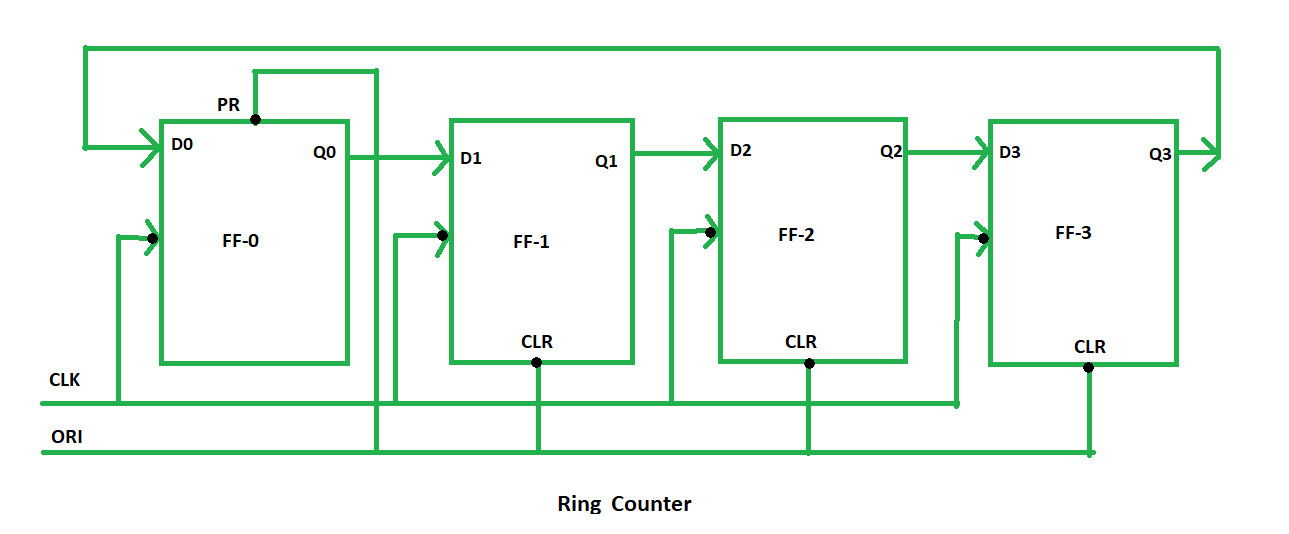
So, for designing a 4-bit Ring counter we need 4 flip-flops as designed below :
Components and Signals
Overriding Input (ORI):
The ORI is used to override the normal functionality of the flip-flops. In this case, Preset (PR) and Clear (CLR) are used as ORI.Preset (PR): When the PR signal is 0, the output of the flip-flop (Q) is set to 1. This is an active-low signal.
Clear (CLR): When the CLR signal is 0, the output of the flip-flop (Q) is set to 0. This is also an active-low signal.
Preset (PR) = 0, Q = 1:
When PR is 0, the output of the flip-flop is forced to 1, regardless of other inputs or the clock signal.
Clear (CLR) = 0, Q = 0:
When CLR is 0, the output of the flip-flop is forced to 0, overriding the other inputs.
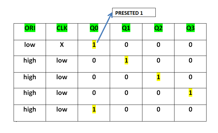
The Preset (PR) and Clear (CLR) signals are used to control the state of the flip-flops.
The ORI input of each flip-flop is connected to the Preset (PR) for FF-0 (the first flip-flop) and to Clear (CLR) for FF-1, FF-2, and FF-3 (the other flip-flops).
At FF-0, when PR = 0, the output Q = 1 is generated, and this creates the initial state of the counter.
At the other flip-flops (FF-1, FF-2, FF-3), the CLR = 0, forcing the outputs Q = 0 at these flip-flops.
This setup results in Pre-set 1 at FF-0, and the other flip-flops hold 0. This "1" at FF-0 then propagates through the flip-flops in a cyclic manner, creating the sequence that is characteristic of the Ring Counter.
This Preseted 1 is generated by making ORI low and that time Clock (CLK) becomes don't care. After that ORI is made to high and apply low clock pulse signal as the Clock (CLK) is negative edge triggered. After that, at each clock pulse, the preseted 1 is shifted to the next flip-flop and thus forms a Ring. In this way can design a 4-bit Ring Counter using four D flip-flops.
Types of Ring Counter:
There are two types of Ring Counter:
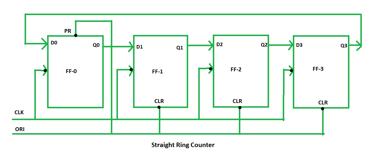
Straight Ring Counter
It is also known as One hot Counter. In this counter, the output of the last flip-flop is connected to the input of the first flip-flop. The main point of this Counter is that it circulates a single one (or zero) bit around the ring. Here, we use Preset (PR) in the first flip-flop and Clock (CLK) for the last three flip-flops.
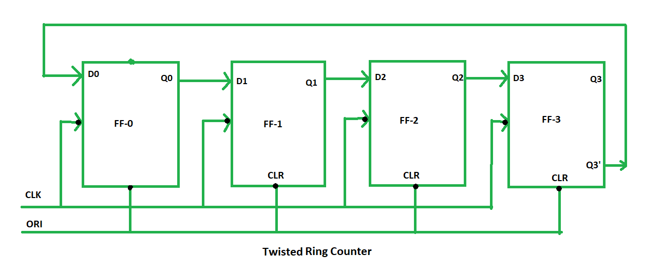
Twisted Ring Counter
It is also known as a switch-tail ring counter, walking ring counter, or Johnson counter. It connects the complement of the output of the last shift register to the input of the first register and circulates a stream of ones followed by zeros around the ring. Here, we use Clock (CLK) for all the flip-flops. In the Twisted Ring Counter, the number of states = 2 X the number of flip-flops.
Ring Counters
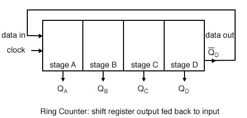
If the output of a shift register is fed back to the input. a ring counter results. The data pattern contained within the shift register will recirculate as long as clock pulses are applied.
For example, the data pattern will repeat every four clock pulses in the figure below. However, we must load a data pattern.
All 0‘s or all 1‘s doesn’t count. Is a continuous logic level from such a condition useful?
We make provisions for loading data into the parallel-in/ serial-out shift register configured as a ring counter below.
Any random pattern may be loaded. The most generally useful pattern is a single 1.
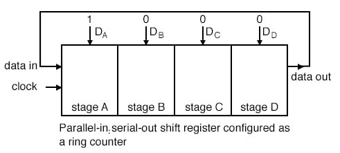
Loading binary 1000 into the ring counter, above, prior to shifting yields a viewable pattern.
The data pattern for a single stage repeats every four clock pulses in our 4-stage example.
The waveforms for all four stages look the same, except for the one clock time delay from one stage to the next. See figure below.
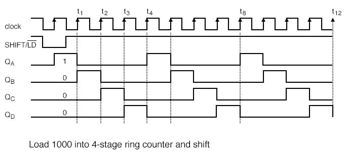
The circuit above is a divide by 4 counter. Comparing the clock input to any one of the outputs, shows a frequency ratio of 4:1.
Q: How may stages would we need for a divide by 10 ring counter?
A: Ten stages would recirculate the 1 every 10 clock pulses.
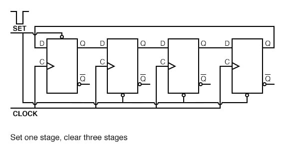
An alternate method of initializing the ring counter to 1000 is shown above. The shift waveforms are identical to those above, repeating every fourth clock pulse.
The requirement for initialization is a disadvantage of the ring counter over a conventional counter.
At a minimum, it must be initialized at power-up since there is no way to predict what state flip-flops will power up in.
In theory, initialization should never be required again. In actual practice, the flip-flops could eventually be corrupted by noise, destroying the data pattern.
A “self correcting” counter, like a conventional synchronous binary counter would be more reliable.
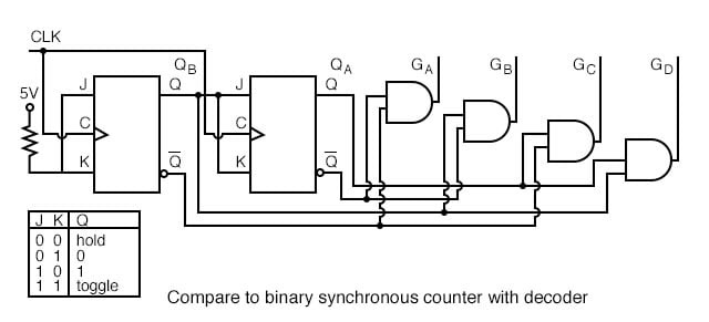
The above binary synchronous counter needs only two stages, but requires decoder gates.
The ring counter had more stages, but was self decoding, saving the decode gates above.
Another disadvantage of the ring counter is that it is not “self starting”.
If we need the decoded outputs, the ring counter looks attractive, in particular, if most of the logic is in a single shift register package. If not, the conventional binary counter is less complex without the decoder.
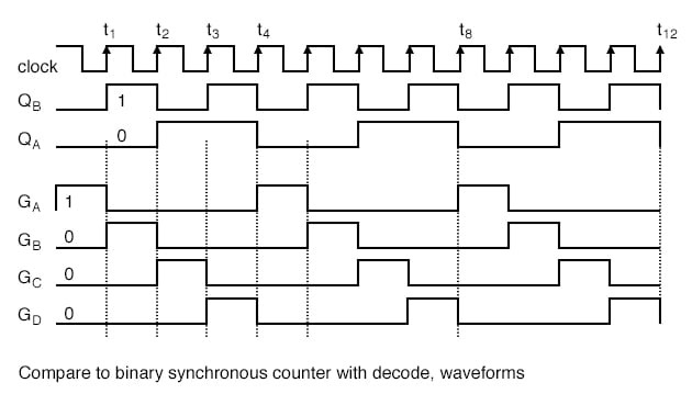
The waveforms decoded from the synchronous binary counter are identical to the previous ring counter waveforms.
The counter sequence is (QA QB) = (00 01 10 11).
Johnson Counter :
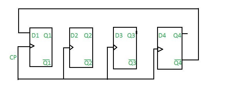
A Johnson counter is a synchronous counter, built using n flip-flops. In this design, the inverted output (complement) of the last flip-flop loops back as the input to the first one—forming a “twisted” feedback ring
A Johnson counter is a type of a synchronous counter with a special counting pattern in this case being Johnson counter. It operates by the complemented output of the last flip flop feed back into the input of the first flip flop. What results from this setup is a series of states which forms a sequence that is not characteristic of normal ring counters.
The Johnson counter can be implemented using n flip flops to count 2n distinct states – a feature that makes it better than a ring counter that uses an equal number of flip flops, as it serves twice the number of states. This counter is used in applications where the number of states is higher than the number of flip-flops; besides, it has a distinguishing feature of self-decodability.
Total number of used and unused states in n-bit Johnson counter:
number of used states=2n
number of unused states=2n - 2*n
Example:
If n=4
4-bit Johnson counter
Initially, suppose all flip-flops are reset.
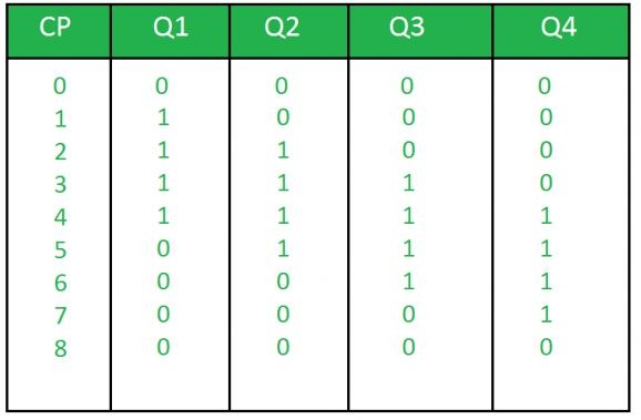
Truth Table
where,
CP is clock pulse and
Q1, Q2, Q3, Q4 are the states.
Question: Determine the total number of used and unused states in 4-bit Johnson counter.
Answer: Total number of used states= 2*n
= 2*4
= 8
Total number of unused states= 2n - 2*n
= 24-2*4
= 8
Difference Between Ring Counter and Johnson Counter
Parameters | Ring Counter | Johnson Counter |
Configuration | A ring counter employs the carry-in of the last flip-flop into the input of the first flip-flop without any manipulation. | In Johnson counter, the complement of output of the last flip-flop is applied to the input of the first flip-flop. |
Number of Flip- Flops | 'n' flip-flops are required to count 'n' states. | 'n' flip-flops are required to count '2n' states. |
Counting Sequence | It counts in a simple binary sequence often having one '1' and the rest '0's in each state. | It counts in a twisted sequence, where the output is a mixture of binary 1s and 0s. |
Number of States | It can Generate 'n' unique states | It can Generate '2n' unique states |
Unused states | None, because all the states are utilized | '2n-2n' states are unused |
Self-Decoding Capability | Its not self-decoding since additional circuitry is needed | Its self-decoding makes it simpler for certain applications |
Circuit Complexity | Since it does not require inversion feedback, thus the circuit is simple | Due to inversion, the circuit is slightly more complex |