
Flip Flops
Flip-Flops
A flip-flop is a fundamental digital electronic circuit that stores a single bit (0 or 1) of binary data, acting as a basic memory element in computers and digital systems, changing its state (outputting 0 or 1) only when triggered by a control signal, like a clock pulse
Types :
S-R Flip-Flop
J-K Flip-Flop
D Flip-Flop
T Flip-Flop
S-R Flip-Flop
This is the simplest flip-flop circuit. It has a set input (S) and a reset input (R). When in this circuit when S is set as active, the output Q would be high and the Q' will be low. If R is set to active then the output Q is low and the Q' is high. Once the outputs are established, the results of the circuit are maintained until S or R get changed, or the power is turned off.
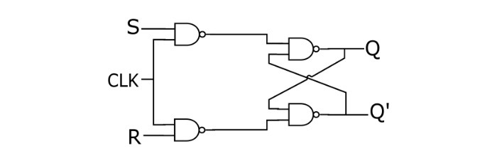
Truth Table of S-R Flip-Flop
S | R | Q | State |
0 | 0 | 0 | No Change |
0 | 1 | 0 | Reset |
1 | 0 | 1 | Set |
1 | 1 | X |
Characteristics Table of S-R Flip-Flop
S | R | Q(t) | Q(t+1) |
0 | 0 | 0 | 0 |
0 | 0 | 1 | 1 |
0 | 1 | 0 | 0 |
0 | 1 | 1 | 0 |
1 | 0 | 0 | 1 |
1 | 0 | 1 | 1 |
1 | 1 | 0 | X |
1 | 1 | 1 | X |
Characteristics Equation of S-R Flip-Flop : Q(t+1)=S+R′ Q(t)
J-K Flip-Flop
Because of the invalid state corresponding to S=R=1 in the SR flip-flop, there is a need of another flip-flop. The JK flip-flop operates with only positive or negative clock transitions. The operation of the JK flip-flop is similar to the SR flip-flop. When the input J and K are different then the output Q takes the value of J at the next clock edge.
When J and K both are low then NO change occurs at the output. If both J and K are high, then at the clock edge, the output will toggle from one state to the other.
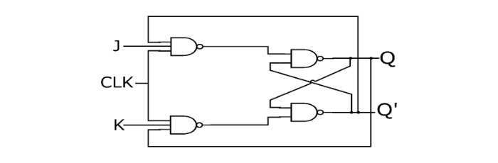
Truth Table of JK Flip-Flop
J | K | Q | State |
0 | 0 | 0 | No Change |
0 | 1 | 0 | Reset |
1 | 0 | 1 | Set |
1 | 1 | Toggles | Toggle |
Characteristics Table of JK Flip-Flop
J | K | Q(t) | Q(t+1) |
0 | 0 | 0 | 0 |
0 | 0 | 1 | 1 |
0 | 1 | 0 | 0 |
0 | 1 | 1 | 0 |
1 | 0 | 0 | 1 |
1 | 0 | 1 | 1 |
1 | 1 | 0 | 1 |
1 | 1 | 1 | 0 |
Characteristics Equation of JK Flip-Flop : Q(t+1)=jk Q(t)′ + K′ Q(t)
D Flip-Flop
In a D flip-flop, the output can only be changed at positive or negative clock transitions, and when the inputs changed at other times, the output will remain unaffected. The D flip-flops are generally used for shift-registers and counters. The change in output state of D flip-flop depends upon the active transition of clock. The output (Q) is same as input and changes only at active transition of clock
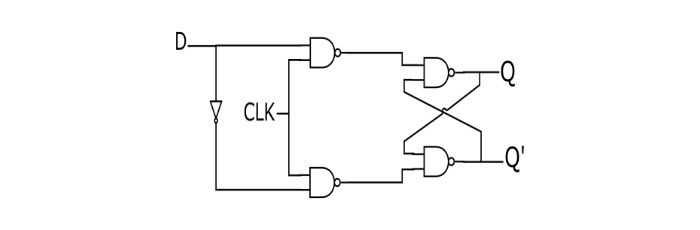
Truth Table of D Flip-Flop
D | Q |
0 | 0 |
1 | 1 |
Characteristics Equation of D Flip-Flops : Q(t+1)=D
T Flip-Flop
A T flip-flop (Toggle Flip-flop) is a simplified version of JK flip-flop. The T flop is obtained by connecting the J and K inputs together. The flip-flop has one input terminal and clock input. These flip-flops are said to be T flip-flops because of their ability to toggle the input state. Toggle flip-flops are mostly used in counters.
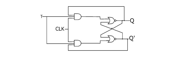
Truth Table of T Flip-Flop
T | Q(t) | Q(t+1) |
0 | 0 | 0 |
0 | 1 | 1 |
1 | 0 | 1 |
1 | 1 | 0 |
Characteristics Equation of T Flip-Flop : Q(t+1)= T′ Q(t)+TQ(t)′ =T⊕Q(t)
Applications of Flip-Flops
Counters
Shift Registers
Storage Registers, etc.