
Counters
Counters in Digital Logic
A Counter is a device which stores (and sometimes displays) the number of times a particular event or process has occurred, often in relationship to a clock signal. Counters are used in digital electronics for counting purpose, they can count specific event happening in the circuit. For example, in UP counter a counter increases count for every rising edge of clock. Not only counting, a counter can follow the certain sequence based on our design like any random sequence 0,1,3,2… .
They can also be designed with the help of flip flops. They are used as frequency dividers where the frequency of given pulse waveform is divided. Counters are sequential circuit that count the number of pulses can be either in binary code or BCD form. The main properties of a counter are timing , sequencing , and counting. Counter works in two modes
Up counter
Down counter
Counter Classification
Counters are broadly divided into two categories
Asynchronous counter
Synchronous counter
1. Asynchronous Counter or Ripple Counters
In asynchronous counter we don’t use universal clock, only first flip flop is driven by main clock and the clock input of rest of the following flip flop is driven by output of previous flip flops. We can understand it by following diagram-
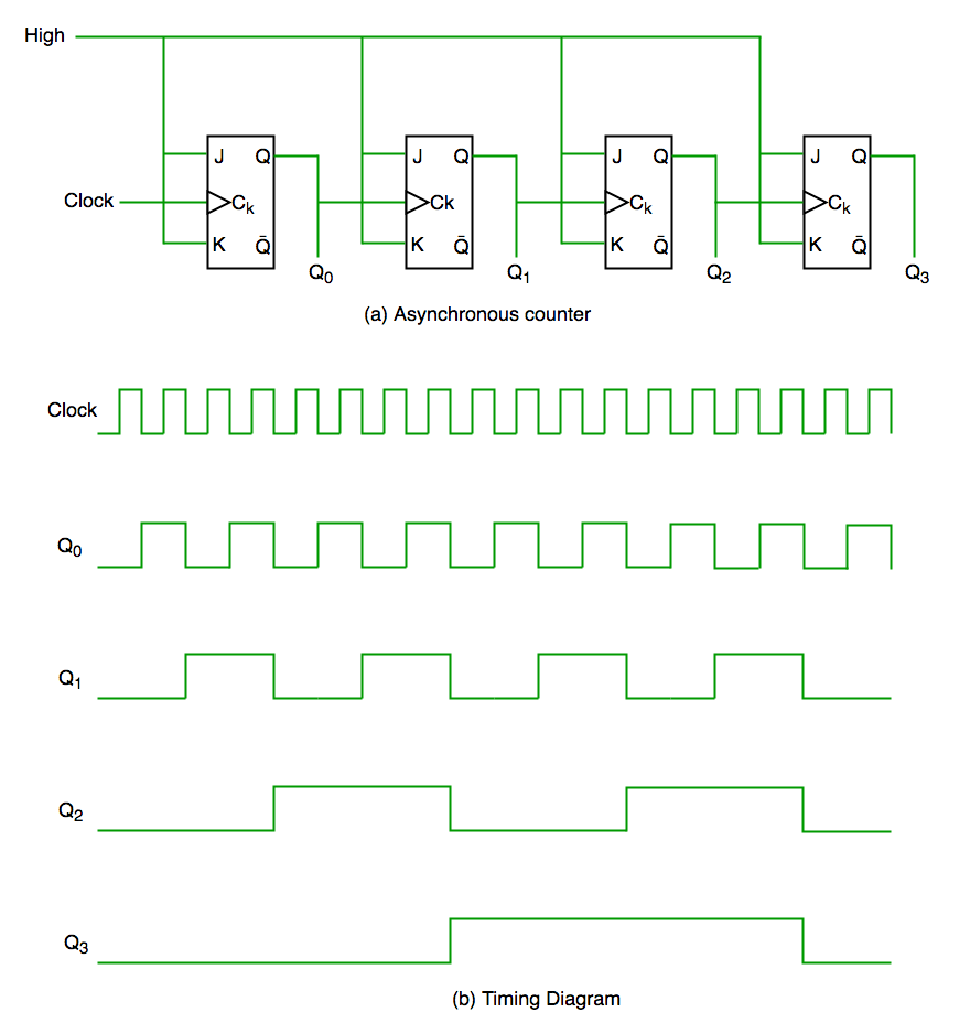
It is evident from timing diagram that Q0 is changing as soon as the rising edge of clock pulse is encountered, Q1 is changing when rising edge of Q0 is encountered(because Q0 is like clock pulse for second flip flop) and so on. In this way ripples are generated through Q0,Q1,Q2,Q3 hence it is also called RIPPLE counter and serial counter. A ripple counter is a cascaded arrangement of flip flops where the output of one flip flop drives the clock input of the following flip flop
2. Synchronous Counter
Unlike the asynchronous counter, synchronous counter has one global clock which drives each flip flop so output changes in parallel. The one advantage of synchronous counter over asynchronous counter is, it can operate on higher frequency than asynchronous counter as it does not have cumulative delay because of same clock is given to each flip flop. It is also called as parallel counter.
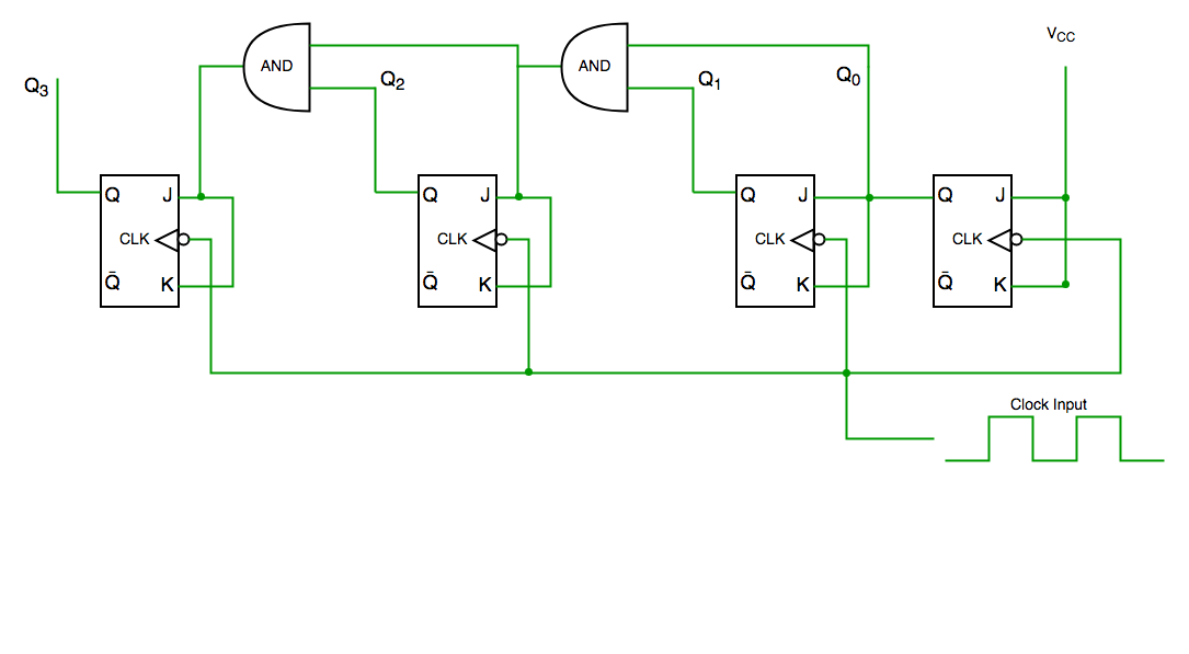
Synchronous counter circuit
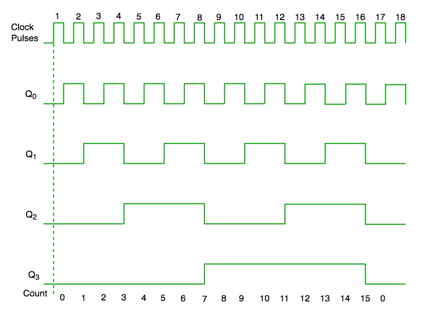
Timing diagram synchronous counter
From circuit diagram we see that Q0 bit gives response to each falling edge of clock while Q1 is dependent on Q0, Q2 is dependent on Q1 and Q0 , Q3 is dependent on Q2,Q1 and Q0.
Classification of Counters
Depending on the way in which the counting progresses, the synchronous or asynchronous counters are classified as follows −
Up Counters
Down Counters
Up/Down Counters
UP/DOWN Counter
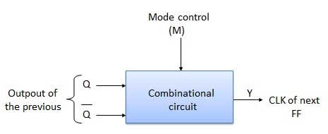
Up counter and down counter is combined together to obtain an UP/DOWN counter. A mode control (M) input is also provided to select either up or down mode. A combinational circuit is required to be designed and used between each pair of flip-flop in order to achieve the up/down operation.
Type of Up/Down Counters
There are two types of up/down counters −
UP/DOWN Ripple Counters
UP/DOWN Synchronous Counter
UP/DOWN Ripple Counters
In the UP/DOWN ripple counter all the FFs operate in the toggle mode. So either T flip-flops or JK flip-flops are to be used. The LSB flip-flop receives clock directly. But the clock to every other FF is obtained from (Q = Q bar) output of the previous FF.
UP counting mode (M=0) − The Q output of the preceding FF is connected to the clock of the next stage if up counting is to be achieved. For this mode, the mode select input M is at logic 0 (M=0).
DOWN counting mode (M=1) − If M = 1, then the Q bar output of the preceding FF is connected to the next FF. This will operate the counter in the counting mode.
Example
3-bit binary up/down ripple counter.
3-bit − hence three FFs are required.
UP/DOWN − So a mode control input is essential.
For a ripple up counter, the Q output of preceding FF is connected to the clock input of the next one.
For a ripple up counter, the Q output of preceding FF is connected to the clock input of the next one.
For a ripple down counter, the Q bar output of preceding FF is connected to the clock input of the next one.
Let the selection of Q and Q bar output of the preceding FF be controlled by the mode control input M such that, If M = 0, UP counting. So connect Q to CLK. If M = 1, DOWN counting. So connect Q bar to CLK.
Block Diagram
Truth Table
[img-placeholder-1767287259719-7x77bfz9u]
Operation
Sr.No | Condition | Operation |
1 | Case 1 − With M = 0 (Up counting mode) | If M = 0 and M bar = 1, then the AND gates 1 and 3 in fig. will be enabled whereas the AND gates 2 and 4 will be disabled. Hence QA gets connected to the clock input of FF-B and QB gets connected to the clock input of FF-C. These connections are same as those for the normal up counter. Thus with M = 0 the circuit work as an up counter. |
2 | Case 2 − With M = 1 (Down counting mode) | If M = 1, then AND gates 2 and 4 in fig. are enabled whereas the AND gates 1 and 3 are disabled. Hence QA bar gets connected to the clock input of FF-B and QB bar gets connected to the clock input of FF-C. These connections will produce a down counter. Thus with M = 1 the circuit works as a down counter. |
Modulus Counter (MOD-N Counter)
The 2-bit ripple counter is called as MOD-4 counter and 3-bit ripple counter is called as MOD-8 counter. So in general, an n-bit ripple counter is called as modulo-N counter. Where, MOD number = 2n.
Type of Modulus
2-bit up or down (MOD-4)
3-bit up or down (MOD-8)
4-bit up or down (MOD-16)
Application of Counters
Frequency counters
Digital clock
Time measurement
A to D converter
Frequency divider circuits
Digital triangular wave generator.