
Part 2
Multiplexers :
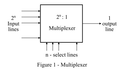
A multiplexer is a combinational circuit with multiple data inputs and a single output, determined by control or select lines. Often referred to as MUX, it requires log2(N)log2(N) selection lines for NN input lines, or equivalently, nn selection lines for 2n2n input lines.
Multiplexer as a digital traffic director. Just like how a traffic light controls which lane of cars can go through an intersection, a multiplexer decides which input signal gets to pass through to the output.
Key Features:
Multiple inputs → Single output
2ⁿ input lines need n control/select lines
Acts like a digital switch
Also called: Data Selector, Many-to-One circuit
Demultiplexer:
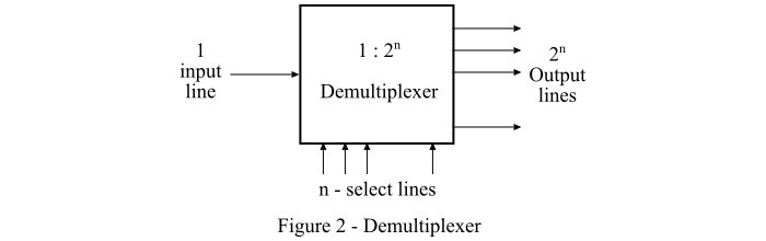
A digital combinational circuit which takes one input signal and generates multiple output signals is known as demultiplexer or DEMUX. As it distributes a single input signal over many output lines, hence it is also referred to as a type of data distributor.
In a demultiplexer, there is only 1 input line and 2n output lines. Where, n denotes the number of select lines. Therefore, it can be noted that a demultiplexer reverses the operation of a multiplexer. The block diagram of a demultiplexer is shown in Figure-2.
Demultiplexers are used in applications where there is a necessity of connecting single source to several destinations, such as in arithmetical and logic unit, in communication system for data transmission, in wavelength routers, etc.
Difference between Multiplexer and Demultiplexer
Both multiplexer and demultiplexer are types of combinational digital circuit that are used in several large-scale digital systems. However, there are many differences between a multiplexer and a demultiplexer, which are highlighted in the following table −
Difference | Multiplexer | Demultiplexer |
Definition | A multiplexer is a combinational digital circuit that takes multiple data inputs and provides only single output. | A demultiplexer is a combinational digital circuit that takes single input and provides multiple outputs. |
Abbreviated name | The abbreviation used to represent the multiplexer is MUX. | The abbreviation used to represent the demultiplexer is DEMUX. |
Input and output lines | Multiplexer has 2n input lines and 1 output line. Where, n is the number of select lines. | Demultiplexer has 1 input line and 2n output lines. Where, n is the number of select lines. |
Also known as | Multiplexer is also known as a "data selector". | Demultiplexer is also known as "data distributor". |
Operating principle | The operating principle of the multiplexer is "many to one". | The operating principle of a demultiplexer is "ne to many". |
Acts as | Multiplexer acts as a digital multi-position switch. | Demultiplexer acts as a digital circuit. |
Conversion technique | A multiplexer performs parallel to serial conversion. | A demultiplexer performs serial to parallel conversion. |
Function of control signal | In case of multiplexer, the function of control signal is to select a specific input that has to be transmitted at the output. | In demultiplexer, the function of control signal is to deliver the single input signal over the multiple output lines. |
Examples | Examples of some common multiplexers are
| Some common demultiplexers are
|
Practical importance | In practice, the multiplexer increases the efficiency of the communication system by enabling the data transmission using a single line. | In practice, the demultiplexer takes the output of a multiplexer and convert in its original form at the receiver end. |
Usage in time-division multiplexing | A multiplexer is used at the transmitter end in the time-division multiplexing (TDM). | The demultiplexer is used at the receiver end in the time-division multiplexing. |
Applications | The multiplexers are commonly used in communication systems, telephone networks, computer memories, etc. | The demultiplexers are used in communication systems, reconstruction of parallel data, ALU, etc. |
Encoder :
An encoder is a combinational logic circuit that is used to convert a normal or familiar information into a coded format. In other words, an encoder is a digital device that coverts a piece of information represented in the form of decimal digits and alphabetic characters into a coded form like binary representation. The operation that the encoder performs is termed as encoding.
In this chapter, we will explain the basics of encoder and commonly used types of encoders.
What is an Encoder?
An encoder is a digital combinational circuit that converts human friendly information into a coded format for processing using machines. In simple words, an encoder converts a piece of information from normal form to coded form. This process is called encoding.
Encoders are crucial components in various digital electronics applications such as data transmission, controlling and automation, communication, signal processing, etc.
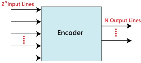
An encoder consists of a certain number of input and output lines. Where, an encoder can have maximum of "2n" input lines whereas "n" output lines. Hence, an encoder encodes information represented by "2n" input lines with "n" bits.
The block diagram of an encoder is shown in the following figure −
Let us now discuss different types of encoders commonly used in digital electronic applications.
Types of Encoders
Some of the commonly used types of encoders in digital electronics −
4 to 2 Encoder
8 to 3 Encoder (Octal Encoder)
Decimal to BCD Encoder
Let us now discuss these three types of most commonly used encoders in detail.
4 to 2 Encoder
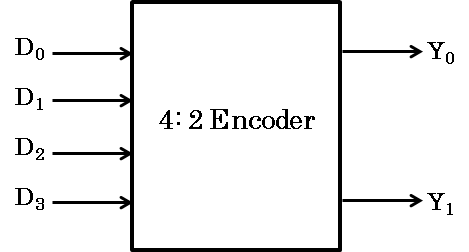
A 4 to 2 Encoder is a type of encoder which has 4 (22) input lines and 2 output lines. It produces an output code (i.e., convert input information in a 2-bit format) depending on the combination of input lines.
The block diagram of a 4 to 2 Encoder is shown in the following figure.
The working of a 4 to 2 Encoder for different input combinations is described in the following truth table −
Inputs | Outputs | ||||
D3 | D2 | D1 | D0 | Y1 | Y0 |
0 | 0 | 0 | 1 | 0 | 0 |
0 | 0 | 1 | 0 | 0 | 1 |
0 | 1 | 0 | 0 | 1 | 0 |
1 | 0 | 0 | 0 | 1 | 1 |
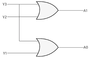
From this truth table, we can derive the Boolean expression for each output of the 4 to 2 Encoder as follows −
Y0 = I1 + I3
Y1 = I2 + I3
It is clear that we can implement the logic circuit of the 4 to 2 Encoder using two OR gates. The following figure depicts the logic diagram of the 4 to 2 Encoder.
Applications of 4 to 2 Encoder
The 4 to 2 Encoder is widely used in the following applications: Data multiplexing, Generating digital control signals, Address decoding applications, Encoding data in digital systems, etc.
Octal to Binary Encoder
The octal to binary encoder is a type of encoder that converts an octal code into binary code. It accepts 8 input lines and produces a 3-bit output depending on the combination of input lines. Therefore, it is also known as 8 to 3 Encoder.
The block diagram of an octal to binary encoder is shown in the following figure −

The following truth table describes the working of an octal to binary encoder −
Inputs | Outputs | |||||||||
I7 | I6 | I5 | I4 | I3 | I2 | I1 | I0 | Y2 | Y1 | Y0 |
0 | 0 | 0 | 0 | 0 | 0 | 0 | 1 | 0 | 0 | 0 |
0 | 0 | 0 | 0 | 0 | 0 | 1 | 0 | 0 | 0 | 1 |
0 | 0 | 0 | 0 | 0 | 1 | 0 | 0 | 0 | 1 | 0 |
0 | 0 | 0 | 0 | 1 | 0 | 0 | 0 | 0 | 1 | 1 |
0 | 0 | 0 | 1 | 0 | 0 | 0 | 0 | 1 | 0 | 0 |
0 | 0 | 1 | 0 | 0 | 0 | 0 | 0 | 1 | 0 | 1 |
0 | 1 | 0 | 0 | 0 | 0 | 0 | 0 | 1 | 1 | 0 |
1 | 0 | 0 | 0 | 0 | 0 | 0 | 0 | 1 | 1 | 1 |
From this truth table, we can write the Boolean expression for the outputs of the octal to binary encoder as follows.
Y0 = I1 + I3 + I5 + I7
Y1 = I2 + I3 + I6 + I7
Y2 = I4 + I5 + I6 + I7
From these expressions, it is clear that the implementation of an octal to binary encoder requires 3 OR gates.
Applications of Octal to Binary Encoder
The octal to binary encoder is used in the following applications −
Data conversion in digital systems.
Conversion of octal memory addresses into binary memory addresses.
In microprocessors and microcontrollers, to convert octal instructions into binary format.
In communication systems, to encode octal data into binary form for transmission, etc.
What is a Decoder?
In digital electronics, a combinational logic circuit that converts an N-bit binary input code into M output channels in such a way that only one output channel is activated for each one of the possible combinations of inputs is known as a decoder.
In other words, a combinational logic circuit which converts N input lines into a maximum of 2N output lines is called a decoder.
Therefore, a decoder is a combination logic circuit that is capable of identifying or detecting a particular code. The operation that a decoder performs is referred to as decoding. A general block diagram of a decoder is shown in Figure-1.
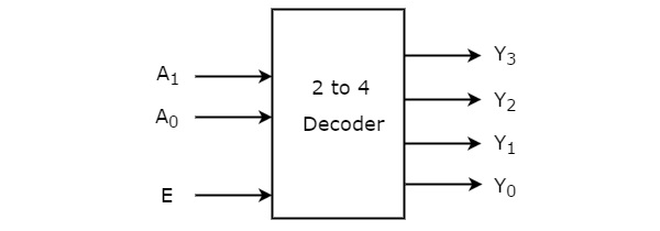
Here, the decoder has N input lines and M (2N) output lines. In a decoder, each of the N input lines can be a 0 or a 1, hence the number of possible input combinations or codes be equal to 2N. For each of these input combinations, only one of the M output lines will be active, and all other output lines will remain inactive.
Types of Decoders
There are several types of decoder present. But, based on the input and output lines present, decoders may classified into the following three types −
2 to 4 Decoder
3 to 8 Decoder
4 to 16 Decoder
Now, let us discuss each type of decoder in detail one by one.
2 to 4 Decoder
The 2 to 4 decoder is one that has 2 input lines and 4 (22) output lines.
When this decoder is enabled with the help of enable input E, then its one of the four outputs will be active for each combination of inputs. The operation of this 2-line to 4-line decoder can be analyzed with the help of its truth table which is given below.
Inputs | Outputs | |||||
E | A | B | Y3 | Y2 | Y1 | Y0 |
0 | X | X | 0 | 0 | 0 | 0 |
1 | 0 | 0 | 0 | 0 | 0 | 1 |
1 | 0 | 1 | 0 | 0 | 1 | 0 |
1 | 1 | 0 | 0 | 1 | 0 | 0 |
1 | 1 | 1 | 1 | 0 | 0 | 0 |
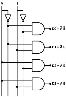
Using this truth table, we can derive the Boolean expression for each output as follows −
Y0 = E · A' · B'
Y1 = E · A' · B
Y2 = E · A · B'
Y3 = E · A · B
As each output term contains products of input variables that can be implemented with the help of AND gates. Therefore, the logic circuit diagram of the 2 to 4 decoder is shown in Figure-3.
Operation
The operation of logic circuit of the 2 to 4 decoder is described as follows −
When enable input (E) is inactive, i.e. set to 0, none of the AND gates will function.
When enable input (E) is made active by setting it to 1, then the circuit works as explained below.
When A = 0 and B = 0, the AND gate 1 becomes active and produces output Y0.
When A = 0 and B = 1, the AND gate 2 becomes active and produces output Y1.
When A = 1 and B = 0, the AND gate 3 becomes active and produces output Y2.
When A = 1 and B = 1, the AND gate 4 becomes active and produces output Y3.